Limited time offer

Get 25% off your order

Use the code below at checkout β€” offer expires soon.

Your promo codeNURSE24
25%
Expires in: 10:00
Claim my 25% discount
LIMITED OFFER Get 25% off β€” use code BESTW25 | βœ” No AI βœ” No Plagiarism βœ” On-Time Delivery βœ” Free Revisions Claim Now

EssayQuest – 24/7 Homework & Research Assistance

Fast, Reliable, and Plagiarism-Free Help for Students in the USA, UK & Australia

EssayQuest – 24/7 Homework & Research Assistance

Fast, Reliable, and Plagiarism-Free Help for Students in the USA, UK & Australia

A voltage waveform from a circuit under test, that you are displaying on an oscilloscope, looks as follows: A voltage waveform from a circuit under test, that you are displaying on an oscilloscope, looks as follows:

Task 1:
Note: You need to have your calculator in radians (RAD) mode for this task (since the angles are given in radians – i.e., Ο€ is featured).
a) A voltage waveform from a circuit under test, that you are displaying on an oscilloscope, looks as follows:

A voltage waveform from a circuit under test, that you are displaying on an oscilloscope, looks as follows:

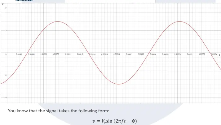
Taking measurements from the oscilloscope display above, determine 𝑉𝑉𝑝𝑝, 𝑓𝑓, π‘Žπ‘Žπ‘Žπ‘Žπ‘Žπ‘Ž βˆ…, and insert those values into the above equation.

Now rearrange your new equation to make the time t, the subject of this formula and hence determine, to within 3 decimal places, the first point in time when the voltage waveform has a magnitude of 5.25 volts.

b) The instantaneous value of the electric field vector close to a radio transmitter at a particular moment in time may be described by:

E = 250∠� 3Ο€ 4 οΏ½ [𝑉𝑉/π‘šπ‘š]

Find the magnitude of the vertical and horizontal components of this field vector.
Note that the symbol ∠ indicates β€˜angle’. Provide a hand-drawn sketch of the electric field vector and its two components, on a set of Cartesian axes.


A voltage waveform from a circuit under test, that you are displaying on an oscilloscope, looks as follows: A voltage waveform from a circuit under test, that you are displaying on an oscilloscope, looks as follows:
Scroll to top